Fixation shapes the physical environment of a healing bone. In finite element analysis, which people often call FEA, fixation stability sets how weight moves through broken spots. This setup changes stress paths, small movements, and how the bone grows back over time. A well-made fixation setup puts the bone pieces back in line. It gives enough strength but does not stop natural healing. The mix of implant stiffness, tool shape, and bone health decides the final success in real patients.
Biomechanical Principles of Fixation in Finite Element Analysis
The mechanics of fixation come down to how weight is shared. The bone and the implant must share this load together. In bone medicine, fixation wants to keep the break steady. At the same time, it must protect the natural weight pathways of the body.
The Concept of Fixation in Orthopedic Biomechanics
Fixation means using tools to hold broken bone pieces steady. Surgeons use tools like plates, screws, or rods for this job. This helper holds the line of the bone. It also brings back weight movement across the broken spot. How well a fixation setup works depends on a few things. The material matters, and the tool shape matters too. Also, the way the metal touches the bone tissue changes the result. For example, titanium plates offer medium stiffness. This trait allows tiny shifts that help a soft bone callus grow. On the other hand, stainless steel tools can be too stiff. They might shield the bone from weight, which can make the bone weak over time.
Finite Element Modeling of Fixation Systems
Finite element analysis lets engineers test hard mechanical actions. They can see how fixation systems act under normal daily weight. Boundary conditions show where the model cannot move. Contact settings copy the friction or bonding between different parts. Material directions show how bone stiffness changes depending on the angle. Testing the computer model against real lab tests or patient data is very important. This step gives the model real trust. Without this check, the math numbers are just guesses. They are not true tools for telling the future.
Influence of Fixation Configuration on Biomechanical Stability
The way you set up a fixation system changes how force spreads through a break. Even tiny shifts in how you turn the implant can change the strain maps a lot.
Role of Implant Positioning and Orientation
Where you put the implant changes where stress builds up. This happens inside both the metal tool and the bone. Putting it in the best spot cuts down on tiny wiggles at the break site. This peace helps a strong callus form. But if the parts do not line up right, the weight spreads unevenly. This bad spread raises the chance of slow healing or broken metal. For instance, anterior spanning attachment devices help bridge gaps. If you put them too close to the prosthesis stem, they can bend too much in one spot. This extra bending hurts long-term stability.
Effect of Fixation Stiffness on Load Transfer
The stiffness of a fixation setup decides how much motion happens where the bone broke. Very stiff setups stop almost all movement between pieces. But this can cause stress shielding. When this happens, the bone around the metal wastes away because it does not get enough exercise. More flexible designs allow small, controlled shifts. These tiny movements help biological healing through secondary bone growth. Finding the perfect middle ground between stiff hold and easy flexing is a big debate in bone mechanics.
Finite Element Evaluation of Anterior Spanning Attachment Devices
In long thigh bone breaks around a past implant, anterior spanning attachment devices act as extra helpers. They bridge the zone between the old prosthesis and the bone.
Structural Behavior Under Axial and Bending Loads
Computer tests measure movement maps, strain energy, and von Mises stress. They test these under straight down weight or bending forces that match normal walking steps. Anterior spanning attachments spread the weight more evenly across the break gap. They do this better than a lone plate on the side. The tool shape changes things too. Its curve and its cross-section area change how well it fights bending and twisting. A tiny shift in design, like moving a screw slightly to the side, can move peak stress numbers by more than 10%. This shift changes how long the metal lasts before it gets tired and breaks.
Interaction Between Prosthesis, Bone, and Fixation Device
The total strength of these setups depends on a main thing. It depends on how the prosthesis stem talks to the hard outer bone through the fixation device. Friction numbers between the surfaces decide how much they slide against each other. A low friction number acts like a smooth, polished stem. Higher numbers act like rough surfaces that grip better. Modeling these touch zones correctly is key. It helps experts predict if a stem will come loose or break in a patient, which people sometimes see after a second replacement surgery.
Material Properties and Their Impact on Fixation Performance
Choosing the right material sets both the mechanical action and the body safety in FEA tests.
Influence of Implant Material on Stress Distribution
Titanium alloys have a great mix of strength and low weight. Their springiness number is close to real outer bone. This close match cuts down on stress jumps where the two materials touch. Stainless steel brings more stiffness. However, it raises the danger of local stress shielding. This shielding leads to thin, weak bones over time. Newer mixed materials use carbon fibers or plastic bases. They can soak up energy well. They also lower top stress marks around screw holes, which often links to fewer tiny cracks spreading.
Modeling Bone Material Heterogeneity in FEA
Bone does not look the same all the way through. Hard outer bone layers wrap around soft, spongy inner bone cores. Their springiness numbers differ a lot, sometimes by ten times. Showing these different zones improves how well computers guess local strain paths around fix spots. Putting CT scan density maps right into the computer mesh allows tests under true daily life settings. In these settings, local changes strongly change the final numbers, like tiny movements or how hard a screw grips before it pulls out.
Optimization Strategies for Enhanced Biomechanical Stability in FEA Models
Smart tuning inside FEA systems refines design choices. It helps find better stability without wasting material.
Parametric Sensitivity Analysis for Design Refinement
Changing design numbers one by one shows what matters most. Engineers can test plate thickness, screw gaps, or offset paths. This test shows which choices change total stiffness or weight sharing the most. This sensitivity test guides exact updates. It is much better than the blind guessing game people often play in early design work. Today, fast computer math programs can test thousands of shapes very quickly. They find smart answers that balance low weight with long life.
Validation Through Experimental Correlation and Computational Convergence Testing
Real-world lab tests are still a must-have tool. They prove the numbers coming out of FEA models are right. Physical tests on real leg bones from donors or plastic fake bones give baseline facts. They show movement and strain under known weights. Mesh tightness tests prove that the math stays steady even when the tiny computer triangles get smaller. This consistency is the hallmark of trustworthy computing. Blending real body shapes from CT scans raises the accuracy of the anatomy. This care ensures the computer tests match true medical life.
Clinical Relevance of Fixation Stability Insights from Finite Element Analysis
The facts learned from FEA turn directly into choices in the operating room. They aim to give patients better healing after deep bone breaks around implants.
Implications for Surgical Planning and Implant Selection
Numbers from FEA help doctors match fixation plans to a single patient’s body shape and bone strength. Measuring how weights share helps a doctor choose between stiff locking plates or semi-flexible bridging tools. This choice depends on how bad the break looks. Helpful models also flag dangers before surgery. They point out zones that might get too much stress, showing where a break could happen later.
Translational Potential Toward Personalized Orthopedic Solutions
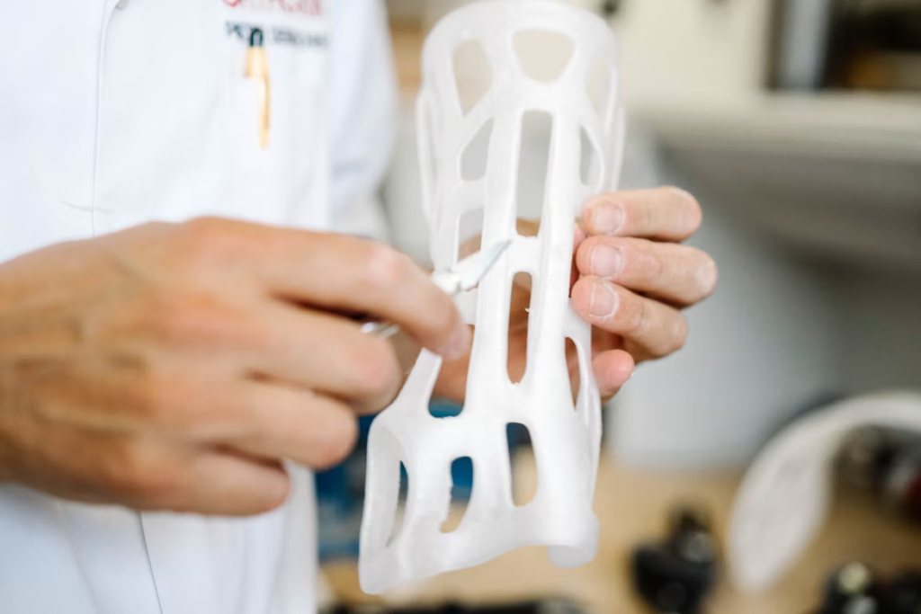
Models made for a single patient open the door for custom fixation tools. Builders make these using 3D printing tools with body-safe metals or mixed materials. They shape them to match the exact curves of a single person’s skeleton. Continuous feedback loops tie computer guesses together with how the patient heals later. This loop refines future medical plans. It moves care toward more trustworthy, custom bone medicine. This is a path that top research centers across the globe follow more and more each day.
FAQ
Q1: What is the main job of fixation in bone mechanics? A: It holds broken bone pieces steady with tools. At the same time, it brings back the natural weight paths across the hurt spot.
Q2: Why do experts use finite element analysis to study fixation setups? A: It gives a close look at how stress spreads, how shapes bend, and how surfaces rub under real weight before doctors try it on a person.
Q3: How does implant stiffness change the way a bone heals? A: Too much stiffness stops the tiny, good movements that bones need. This lack of stress makes bones thin. Medium flexibility helps a bone callus form, which aids natural repair.
Q4: What things make an FEA test trustworthy? A: You need to set the holding spots right. You must model the material accurately, including how its strength changes with direction. You also need mesh size checks and real lab tests to prove the model works.
Q5: How does FEA help make custom bone tools for patients? A: It takes a patient’s own scan pictures and puts them into the model. This step lets engineers design custom implants that fit one person’s body perfectly, and then builders print them using modern 3D machines.